F-15C Cockpit Instruments
The F-15C cockpit is organized around three combat references: the HUD, the Vertical Situation Display (VSD), and the Tactical Electronic Warfare System (TEWS) display. Engine, navigation, fuel, armament, and countermeasure instruments are grouped below and around those displays so the pilot can cross-check aircraft state while staying focused on the fight.
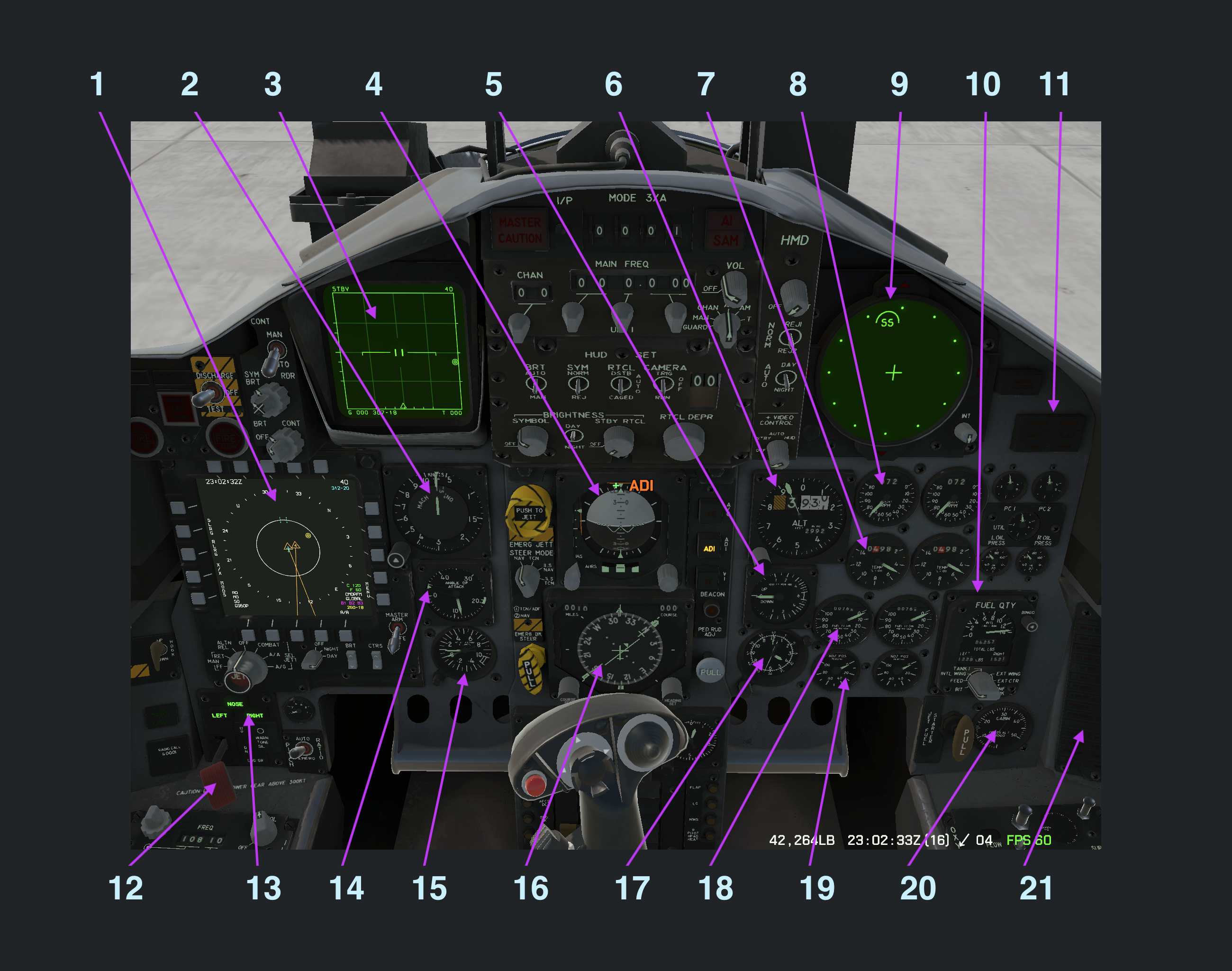
Cockpit Panel Index
| No. | Instrument | Primary use |
|---|---|---|
| 1 | Multi-Purpose Color Display (MPCD) | Weapon, gun, countermeasure, and external tank status |
| 2 | Indicated Airspeed and Mach Indicator | IAS in knots and Mach number |
| 3 | Vertical Situation Display (VSD) | Radar, datalink, and target information |
| 4 | Attitude Director Indicator (ADI) | Pitch, bank, turn, and slip reference |
| 5 | Vertical Velocity Indicator (VVI) | Climb or descent rate |
| 6 | Barometric Altimeter | Pressure altitude in feet |
| 7 | Fan Turbine Inlet Temperature (FTIT) | Engine temperature |
| 8 | Tachometer | Engine RPM percentage |
| 9 | Tactical Electronic Warfare System (TEWS) | Radar warning and ECM state |
| 10 | Fuel Quantity Indicator | Internal, external, and total fuel |
| 11 | Chaff and Flare Indicators | Countermeasure dispense and low-count state |
| 12 | Landing Gear Handle | Gear command |
| 13 | Landing Gear Position Indicator | Gear locked/down status |
| 14 | Angle of Attack Indicator | AoA units for maneuvering and landing |
| 15 | Accelerometer | Current and recorded G-load |
| 16 | Horizontal Situation Indicator (HSI) | Heading, course, bearing, and waypoint distance |
| 17 | Aircraft Clock | Time reference |
| 18 | Engine Fuel Flow Indicator | Fuel flow per engine |
| 19 | Engine Nozzle Position Indicator | Exhaust nozzle opening |
| 20 | Cabin Pressure Gauge | Equivalent cabin altitude |
| 21 | Warning Light Panel | System warning annunciators |
| 22 | Emergency Jettison Button | Emergency release of eligible external stores |
| 23 | Steering Mode Selector | NAV, TCN, ILS/NAV, or ILS/TCN steering source |
| 24 | Hydraulic Pressure Indicators | PC1, PC2, and utility hydraulic pressure |
| 25 | Engine Oil Pressure Indicators | Left and right engine oil pressure |
Combat Displays
Vertical Situation Display (VSD)
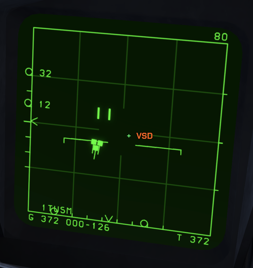
The VSD is the F-15C radar display. It shows the radar search volume, target returns, lock state, and target details used for beyond-visual-range employment. Radar procedures and symbology are covered in the radar chapter.
Tactical Electronic Warfare System (TEWS)
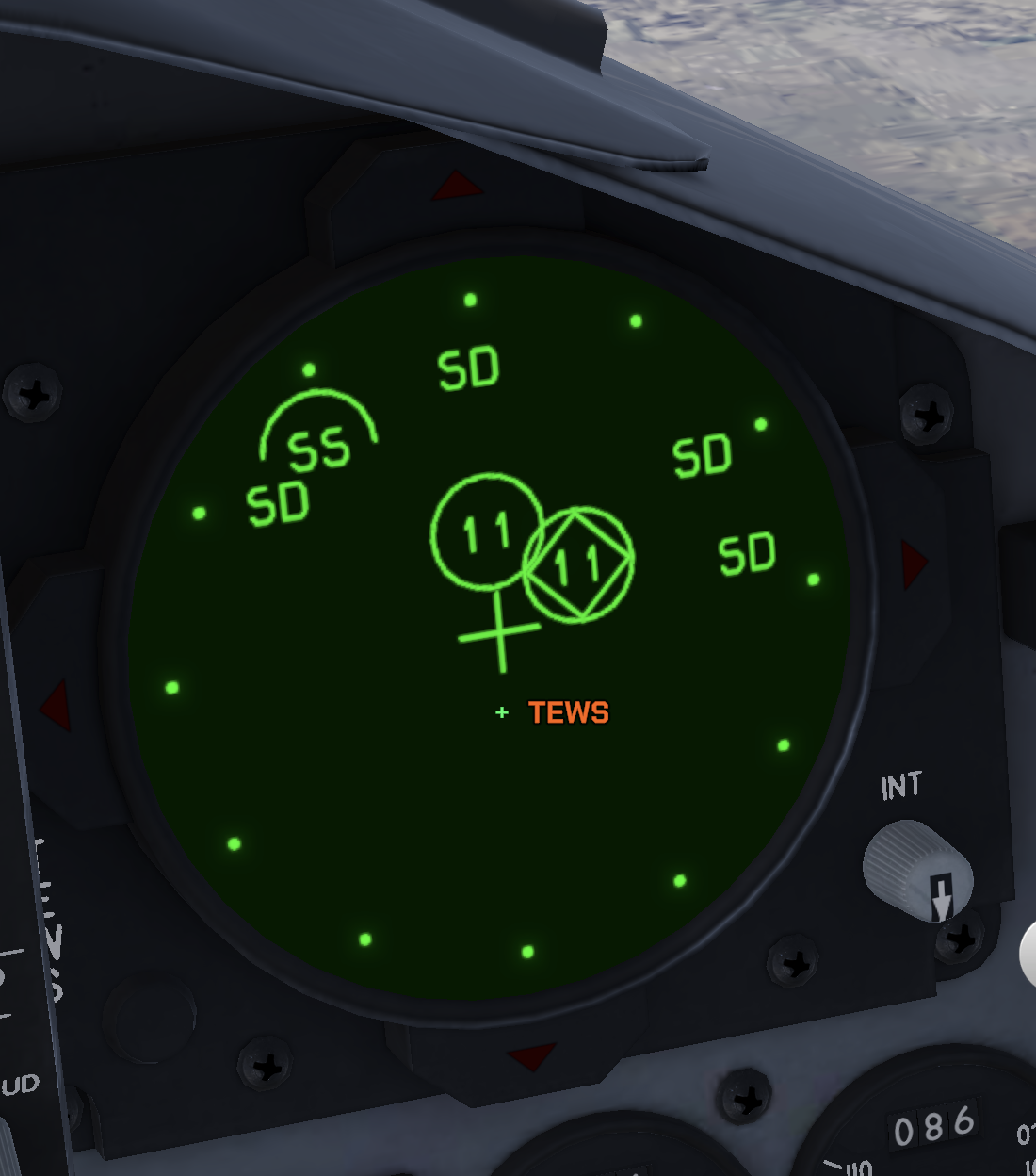
The TEWS display is the pilot's radar warning display. It presents radar emitters around the aircraft symbol, prioritizes the most dangerous threat, and shows missile launch indications and ECM status.
Multi-Purpose Color Display / Weapons Control Panel
SIT Situational Display
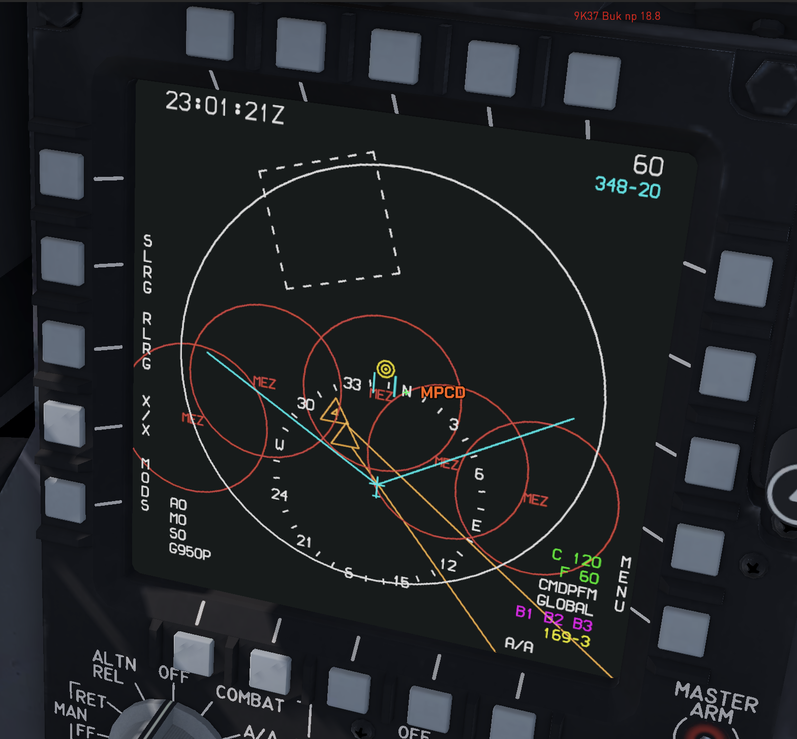
The tactical situation display provides a top-down view of the battlespace. Through the datalink, it shows information about ownship, friendly aircraft, and hostile aircraft. It can also display multiple types of geofences, a compass, Zulu time, and bullseye coordinates. The cursor can be slaved to the VSD or operated independently in an unslaved mode.
AA Weapon Status Panel
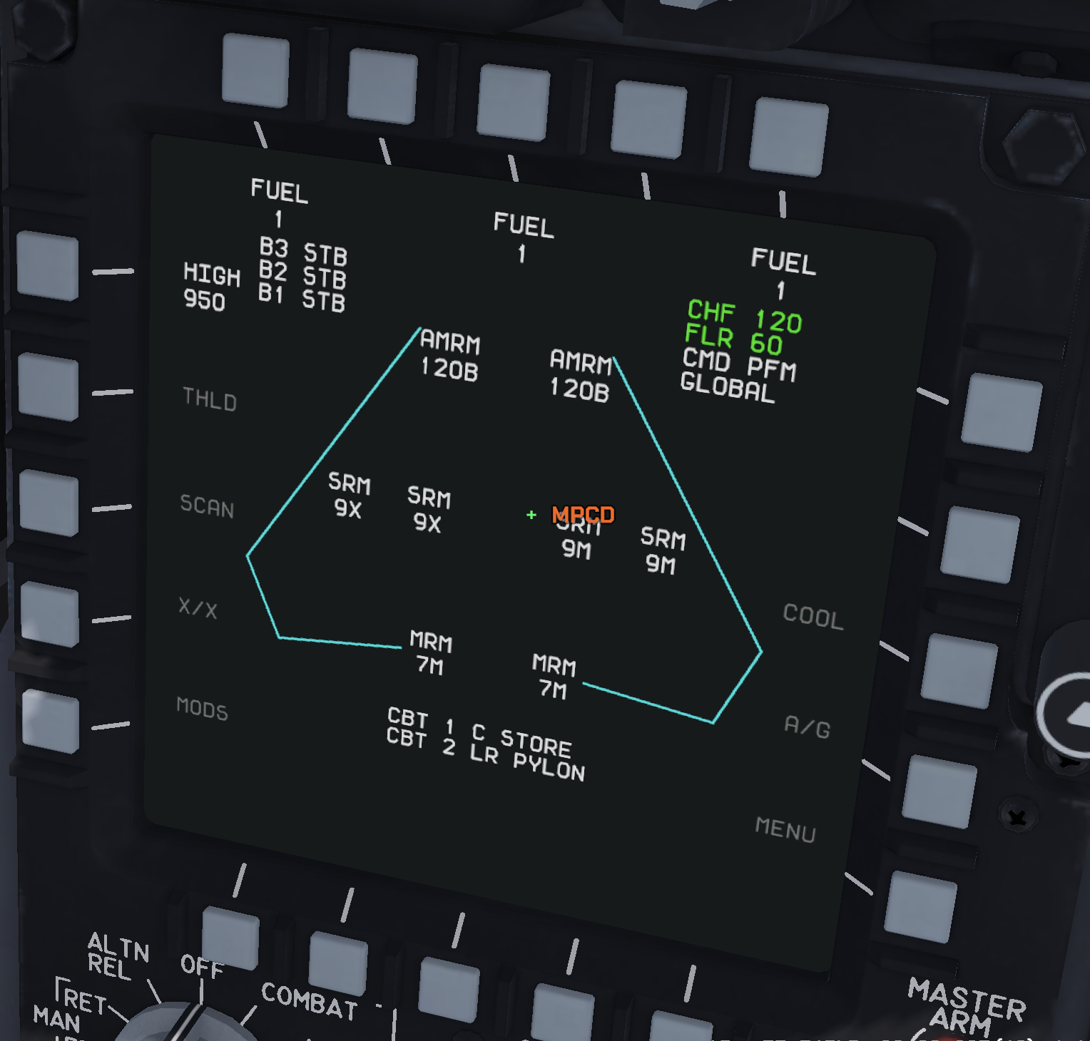
The AA page shows external tanks, weapon types, gun ammunition, and remaining chaff and flares. FUEL identifies an installed tank; PYLON identifies an empty station. See the MPCD chapter for weapon selection and the complete display.
Flight Instruments
Landing Gear Handle
The landing gear handle commands landing gear extension and retraction.
Landing Gear Position Indicator
The landing gear position indicator confirms when the landing gear is locked down.
Indicated Airspeed and Mach
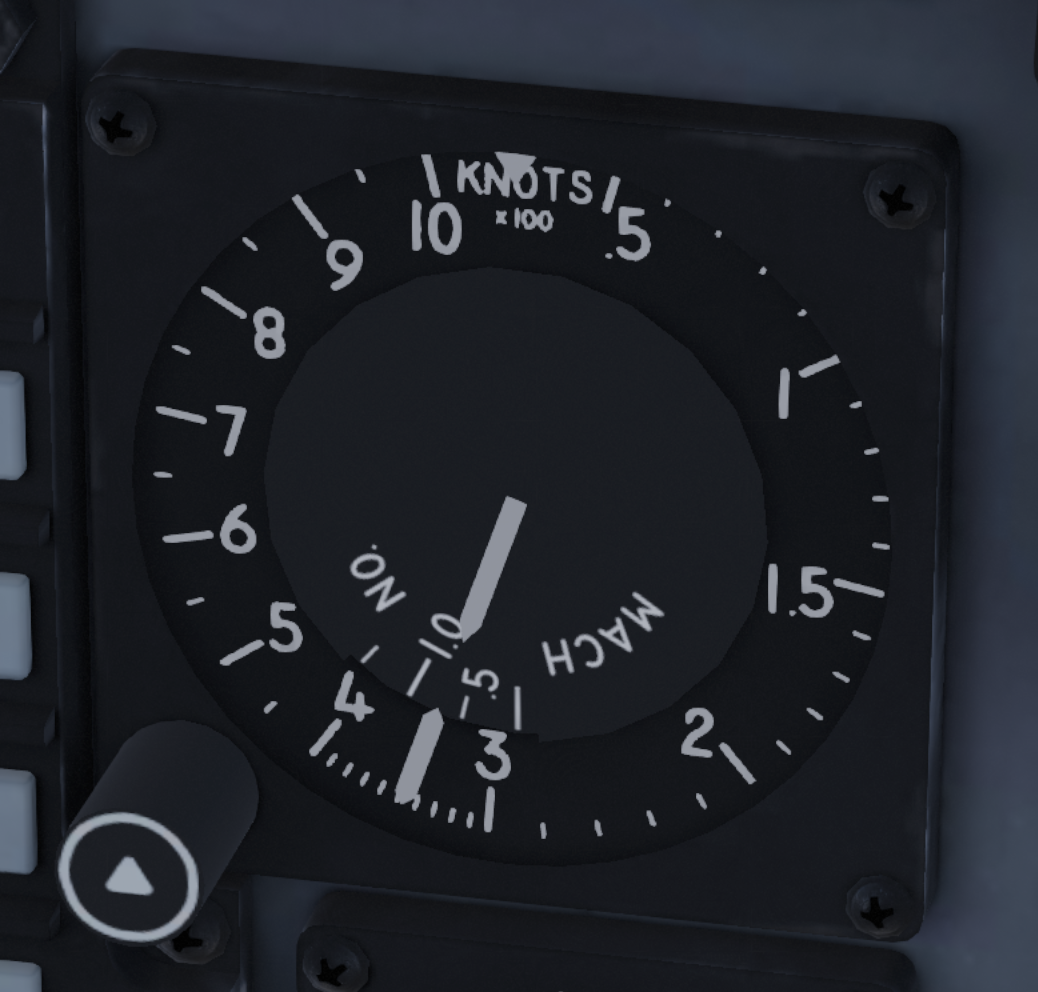
The airspeed and Mach indicator is mounted to the right of the MPCD. The fixed scale reads indicated airspeed from 50 to 1000 knots. The Mach pointer becomes useful above roughly 200 knots.
Angle of Attack Indicator
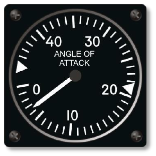
The AoA indicator shows angle of attack in F-15 units, not geometric degrees. Use it during approach, slow-speed maneuvering, and high-AoA recovery. For landing, the normal target is about 20 to 22 units.
Accelerometer
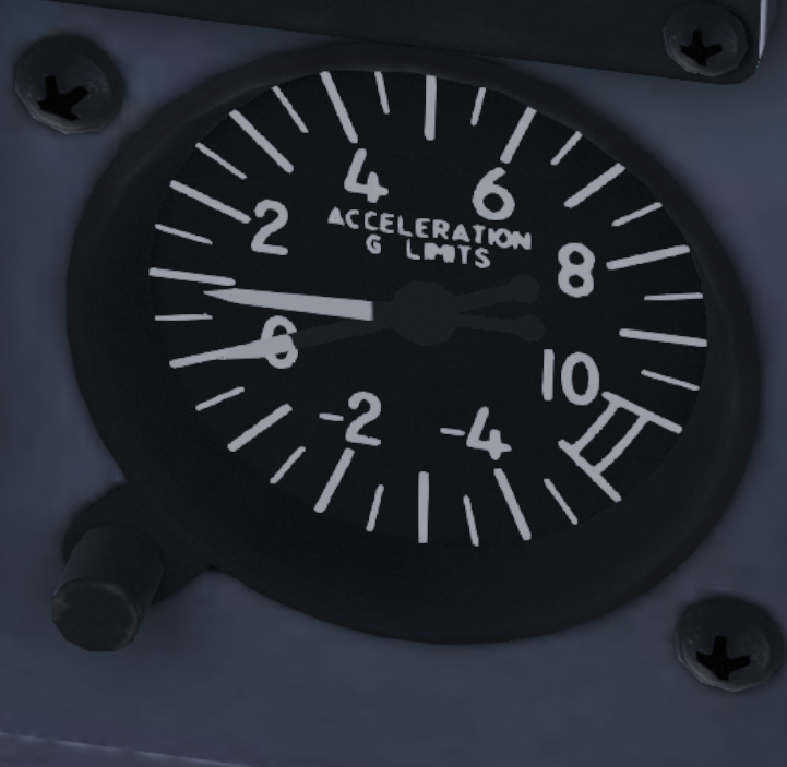
The accelerometer shows current G-load and records the maximum positive and negative G reached during the sortie. Treat it as a structural health cross-check after aggressive maneuvering.
Central ADI, HSI, and adjacent controls
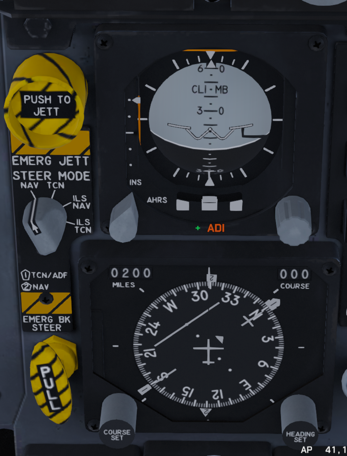
Attitude Director Indicator
The ADI provides the primary pitch-and-bank attitude reference. The rotating sphere uses 5-degree pitch graduations and 10-degree bank graduations, with larger marks every 30 degrees. The vertical and horizontal steering bars provide command guidance for the selected navigation source, while the lower turn-and-slip indication helps coordinate turns. The selector beside the instrument chooses the INS or AHRS attitude reference when that function is available.
Horizontal Situation Indicator
The HSI presents a plan view of the navigation situation. The rotating compass card places aircraft heading under the top index; the course arrow and deviation bar show the selected course and lateral error. The upper-left counter shows distance in nautical miles, and the upper-right counter shows the selected course. The COURSE SET and HEADING SET knobs adjust those references. During an ILS approach, the course-deviation indications are used with the ADI and HUD guidance.
Emergency Jettison Button
The guarded yellow-and-black PUSH TO JETT button, immediately left of the ADI, initiates emergency jettison of eligible external stores. Use it only when immediate load shedding is necessary; the exact stores released depend on the current aircraft configuration and mission rules.
Steering Mode Selector
The selector below the emergency-jettison button chooses which navigation source drives steering information on the HSI, ADI, and HUD:
- NAV: route and steerpoint navigation.
- TCN: TACAN bearing, distance, and selected-course guidance.
- ILS NAV: ILS localizer and glideslope guidance combined with NAV steering.
- ILS TCN: ILS guidance combined with TACAN steering.
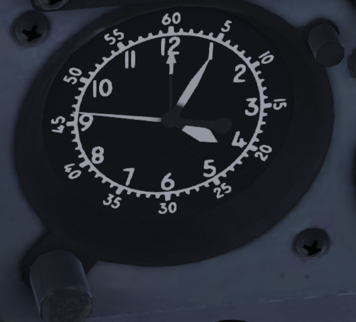
Aircraft Clock
The aircraft clock provides the cockpit time reference and displays Zulu time used for mission timing and navigation cross-checks.
Altimeter and vertical-velocity instruments
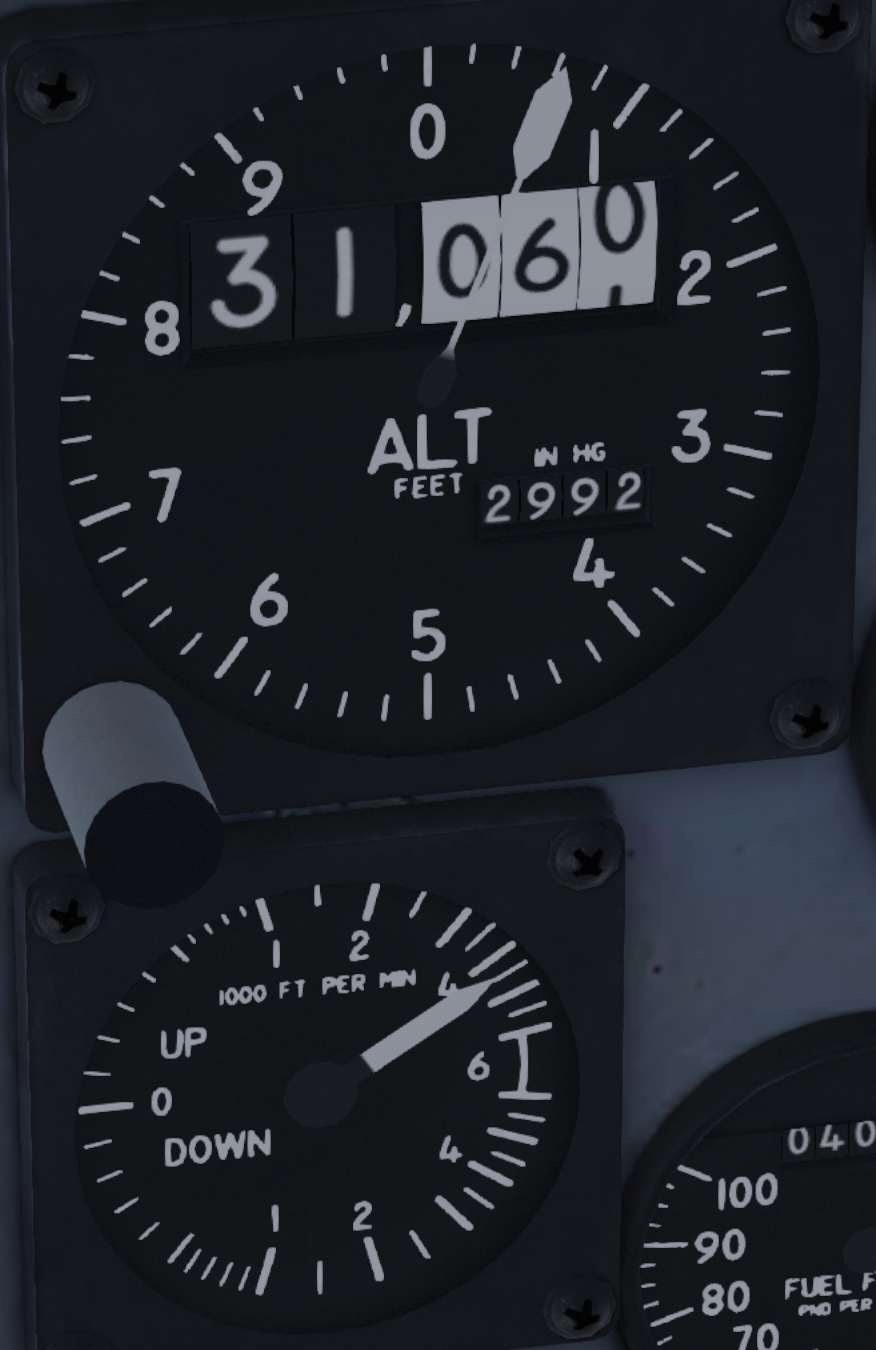
Barometric Altimeter
The counter-pointer altimeter displays altitude in feet. The drum counter gives the main altitude value while the pointer provides the finer part of the reading. Use the pressure-setting knob to enter the required local altimeter setting; an incorrect setting produces an incorrect indicated altitude.
Vertical Velocity Indicator
The VVI shows climb or descent rate in thousands of feet per minute. Clockwise movement indicates climb; counter-clockwise movement indicates descent.
Engine and Fuel Instruments
Engine RPM and temperature
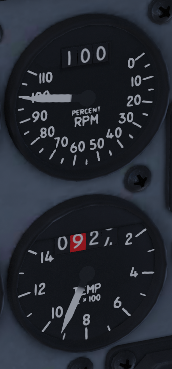
Tachometer
The paired tachometers show left and right engine RPM from 0 to 110 percent. Use the pointer and counter together during engine start, taxi, takeoff checks, and throttle cross-checks.
Fan Turbine Inlet Temperature
The paired FTIT gauges show turbine temperature from 0 to 1400 °C. The pointer supplies the continuous reading and the counter makes the value easier to confirm. An abnormally high value indicates excessive turbine temperature and requires prompt attention.
Fuel flow and exhaust nozzle position
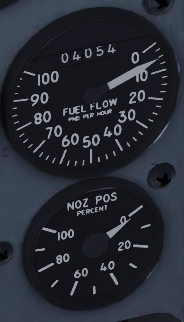
Engine Fuel Flow
The fuel-flow indication shows total fuel supplied to the engines, including afterburner flow, in pounds per hour. Use it with the fuel-quantity display to monitor consumption and identify unexpected engine or fuel-system behavior.
Engine Nozzle Position
The nozzle gauges show exhaust nozzle opening percentage relative to fully open. Nozzle position changes with engine power and afterburner operation.
Hydraulic and engine-oil pressure
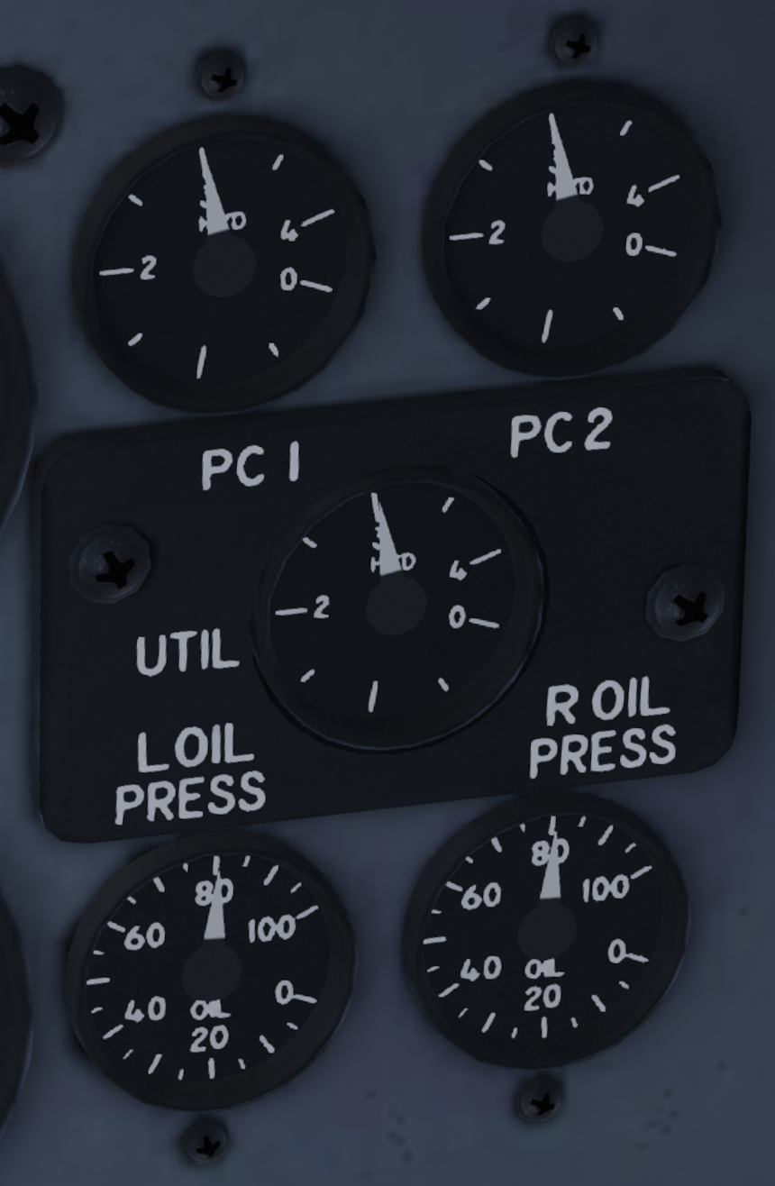
Hydraulic Pressure Indicators
The three hydraulic gauges show PC1, PC2, and UTIL pressure from 0 to 4000 psi. PC1 and PC2 supply the flight-control system, while the utility system supplies services such as landing gear, brakes, and nosewheel steering. Normal operating pressure is approximately 3000 psi; a major drop or a zero reading helps identify the affected hydraulic system.
Engine Oil Pressure Indicators
The two lower gauges show left- and right-engine oil pressure from 0 to 100 psi. Compare both engines and cross-check any low reading with the corresponding caution indication.
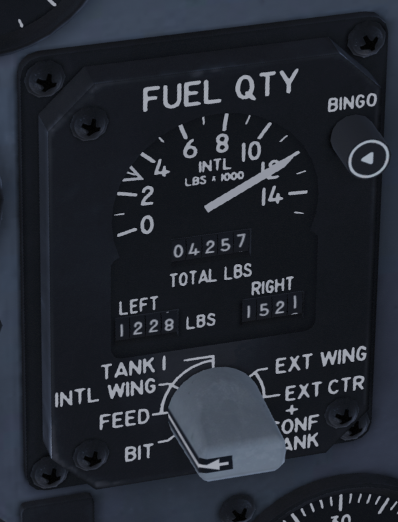
Fuel Quantity
The pointer indicates total internal fuel in thousands of pounds. The upper counter shows total fuel, while the lower LEFT and RIGHT counters and selector allow individual tank quantities and indicator checks to be monitored.
Pressure and Countermeasures
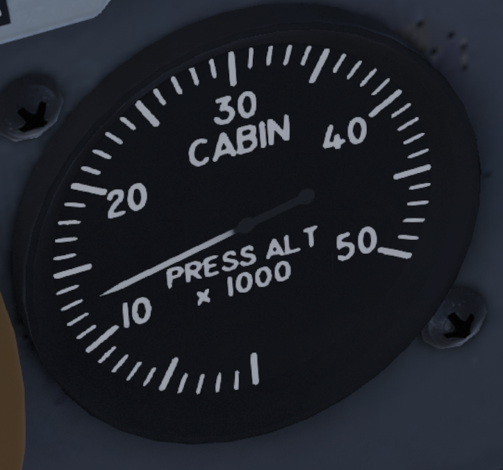
Cabin Pressure Gauge
The cabin pressure gauge displays equivalent cabin altitude. If damage or pressurization failure causes the indicated cabin altitude to rise toward 10000 ft, descend promptly.
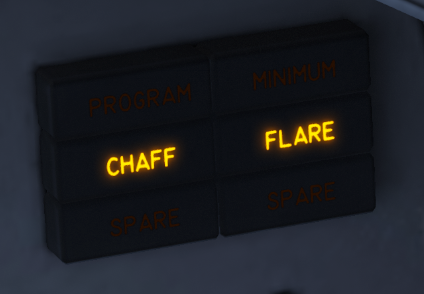
Chaff and Flare Indicators
The chaff and flare lights flash for about three seconds during dispense. The minimum warning light illuminates when remaining countermeasure quantity is critically low.
Warning Light Panel
The warning light panel annunciates aircraft system warnings.