F-15C Flight Dynamics and Performance
The F-15C has a high thrust-to-weight ratio and strong control authority, but it must still be flown inside its aerodynamic and structural limits. This chapter summarizes normal flight technique and the performance limits described in the manual.
Takeoff
Line up on the runway centerline and stabilize before applying takeoff power.
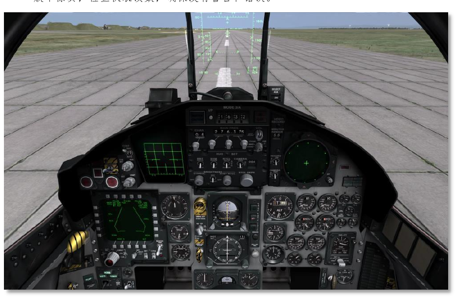
Normal takeoff sequence:
- Taxi 10 to 15 meters to align the nosewheel and aircraft with the runway.
- Stop smoothly on the centerline.
- Advance throttles to about 80 percent RPM and check engine instruments.
- Lower flaps and verify no warning lights require abort.
- Release brakes and advance to military power or maximum afterburner.
- At about 100 knots, begin a smooth aft stick input.
- Rotate to about 10 degrees pitch.
- After liftoff, retract landing gear and flaps.
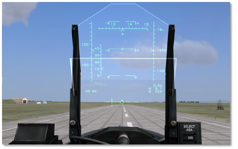
For minimum ground roll, maintain about 12 degrees pitch after the nosewheel lifts. Avoid over-rotation and tail strike.
Climb
With military power, climb from 350 knots IAS to Mach 0.9, then hold Mach 0.9. With maximum power, climb from 350 knots IAS to Mach 0.95. If climb angle becomes excessive and airspeed decays, lower the nose and recover energy.
Cruise and Endurance
For efficient flight, monitor AoA, fuel flow, altitude, and throttle setting. The manual highlights AoA-based performance references:
- Maximum range flight: approximately 12 AoA units.
- Maximum endurance flight: approximately 14.5 AoA units.
Use maximum endurance when holding or waiting; use maximum range when distance matters.
Approach and Landing
Recommended approach technique:
- Use about 250 knots for the initial approach.
- Reduce throttle to roughly 72 percent and lower the nose to descend.
- Use speed brake as required to manage descent without overspeeding.
- On final, slow to 200 to 250 knots, lower gear and flaps, then stabilize.
- Maintain about 180 knots and 20 to 22 AoA units on final.
- At touchdown, reduce throttles to idle.
- Hold about 13 degrees nose-up for aerodynamic braking.
- Keep pitch below about 15 degrees to avoid tail strike.
- Lower the nose below about 90 knots and apply wheel brakes.
Flight Envelope
The flight envelope defines where the aircraft can maintain level flight at a given altitude and Mach number.
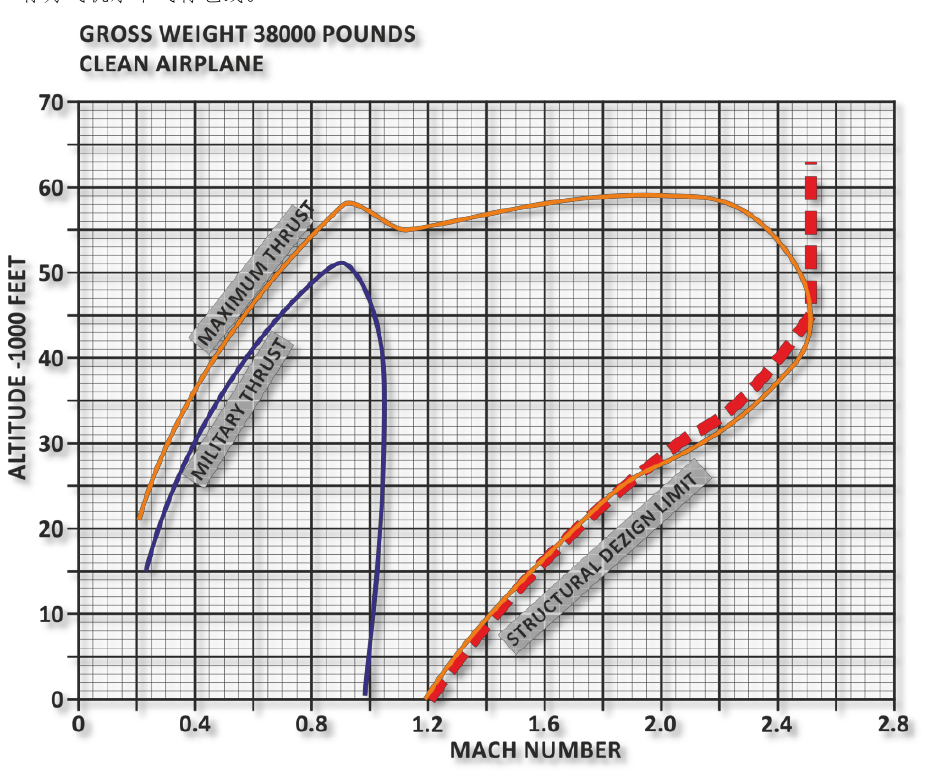
The manual's envelope references are based on specific test assumptions, including clean aircraft configuration, defined gross weight, and standard pressure and temperature. Treat the chart as a performance guide rather than a guarantee for every loadout.
Control Augmentation and High AoA
The F-15C uses control augmentation to improve stability and handling. At moderate AoA, lateral stick input remains effective. At high AoA, rudder becomes increasingly important for roll control.
Handling notes:
- Below about 30 AoA units, lateral stick input is still effective.
- Above about 30 AoA units, rudder becomes the primary roll control.
- Above about 35 AoA units, roll rate drops rapidly.
- Buffeting begins before the aircraft reaches departure; treat it as feedback, not decoration.
Low-Speed and Tail-Slide Hazards
At low speed, control response is reduced and recovery margin shrinks. A very steep climb can develop into a tail slide if the aircraft loses forward speed. During a tail slide, airflow over the control surfaces can become unpredictable and engine/compressor behavior may become unstable.
To recover, unload, neutralize excessive inputs, let the nose fall, and regain airspeed before pulling.
Terrain-Following Flight
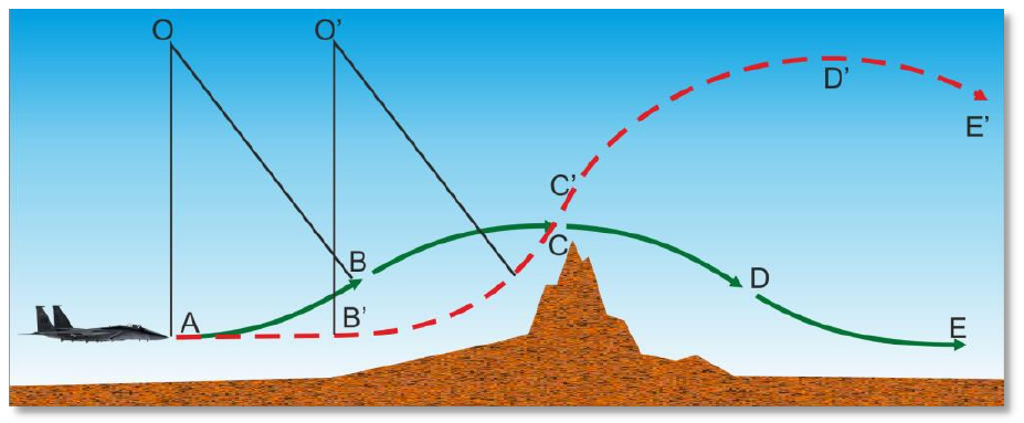
Very low-level flight reduces enemy detection time but increases workload and risk:
- Fuel burn rises.
- Visual detection range is reduced for both sides.
- Radio and control coverage may be degraded.
- Maneuver options are constrained by terrain.
- Formation flight becomes harder and more dangerous.
G-Load Performance
Load factor is lift divided by aircraft weight. Structural and thrust-limited G both matter.
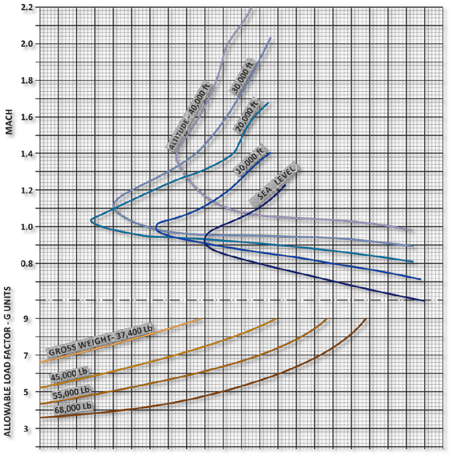
Instantaneous G is a short-duration structural and aerodynamic limit. It can give rapid nose position but usually costs speed.
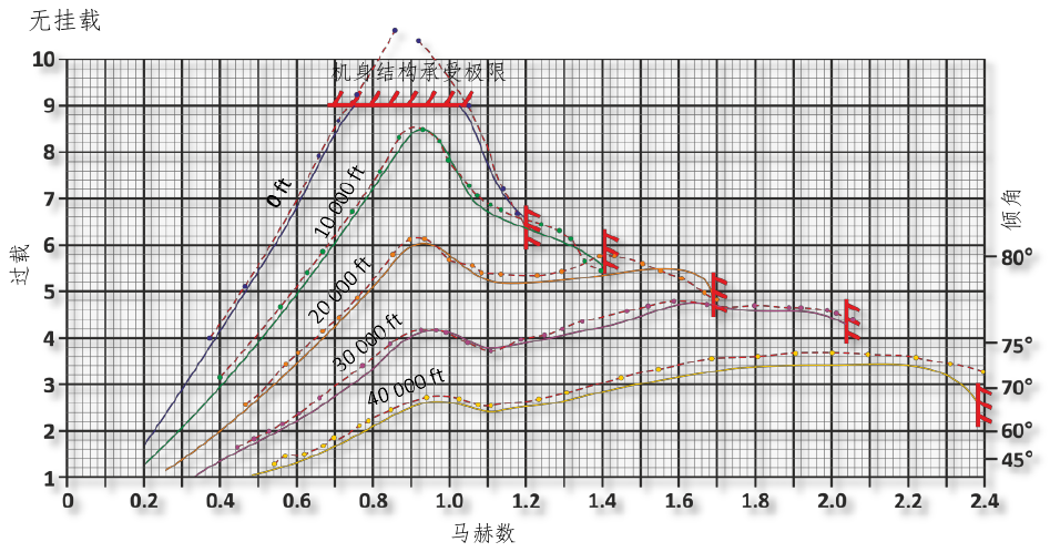
Sustained G is the load factor the aircraft can hold without continued speed loss at a given condition. It is affected by altitude, Mach, weight, stores, and atmospheric conditions.
Longitudinal G limits also vary with altitude and speed.
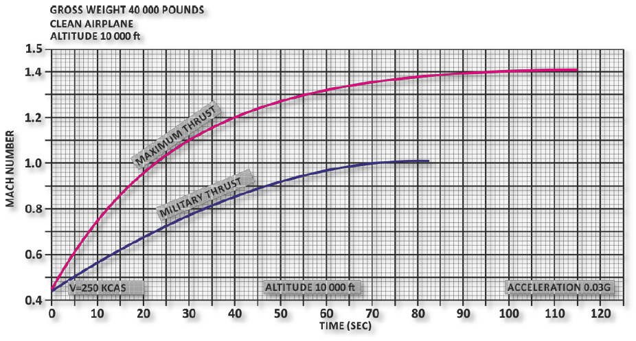
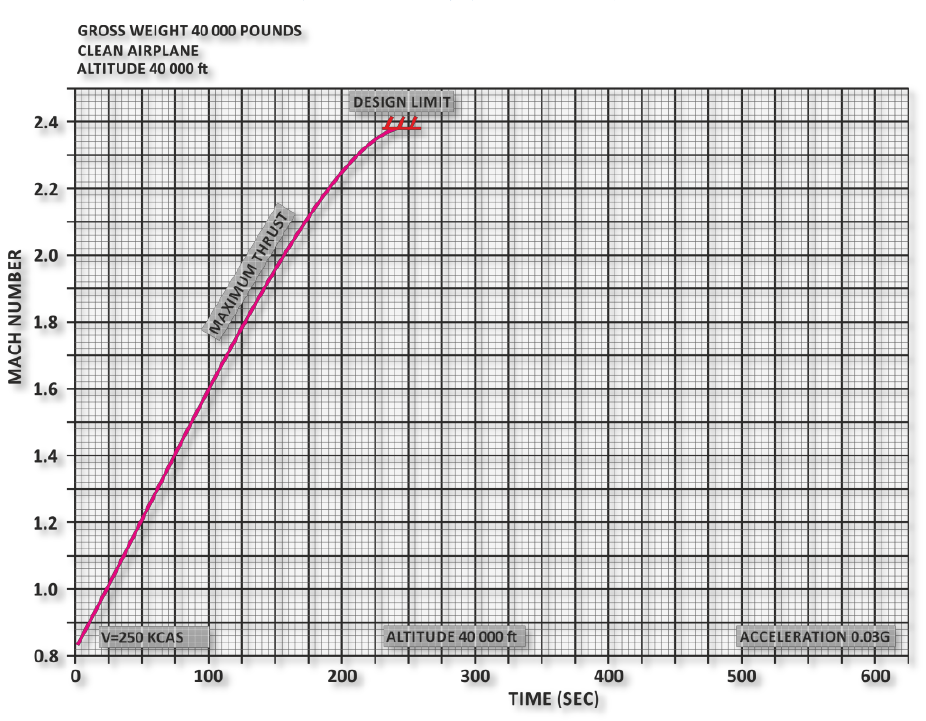
External Factors
Performance changes with:
- Weight: More weight reduces available maneuvering margin.
- External stores: Tanks and weapons add drag and may reduce allowable G.
- Atmosphere: High temperature reduces engine thrust and sustained turn performance.
- Altitude: Thin air reduces drag but also changes available lift and engine behavior.
The practical rule is simple: a clean, light, fast F-15C can fight harder than a heavy, draggy, slow one.